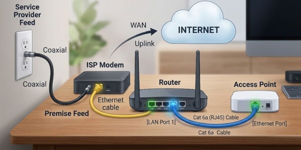
The CompTIA Network+ 1.3.9 simulation lab tests your ability to extend a wired local area network by integrating a wireless access point (WAP). In this lab, you transition a home office from a strictly wired architecture to a hybrid network that supports mobile client connectivity.
Completing the lab requires selecting the correct wireless access point from an equipment shelf, establishing physical Ethernet and power connections, turning on the laptop’s physical wireless adapter, and configuring an automatic Wi-Fi connection to the HomeNet-AC network.
Beyond following the step-by-step click path required by the test simulator, understanding the underlying network concepts is critical for the exam. This guide walks through the required physical and logical steps while detailing why specific standards, cable types, and device configurations are selected.
What the Home Wireless Network Lab Requires
The lab scenario places you in a simulated home office containing an existing wired router connected to a power distribution unit (PDU). Your objective is to deploy a wireless access point that bridges wireless clients to the existing wired infrastructure without replacing the primary router.
The simulation environment requires fulfilling several specific hardware and network criteria:
- The existing router: Acts as the primary gateway, providing local IP address assignment and upstream network access.
- The wireless access point: Must support transmission speeds up to 600 Mbps while maintaining backward compatibility with legacy 2.4 GHz wireless standards.
- The laptop client: Equipped with an internal wireless network interface card (NIC) that must be enabled using a hardware switch.
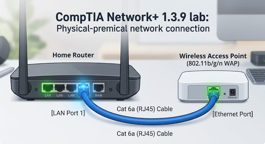
- Ethernet media: A designated Category 6a (Cat 6a) patch cable with RJ45 modular connectors to bridge the access point to an available LAN port on the router.
- Power infrastructure: A dedicated power adapter connecting the access point to an available outlet on the rack-mounted PDU.
- Wireless SSID configuration: Connecting the client to the HomeNet-AC network identifier and configuring the connection to establish automatically.
Requirements Checklist
Before starting the simulation steps, verify the target parameters:
- Target SSID: HomeNet-AC
- Supported standards: 802.11b, 802.11g, 802.11n
- Maximum theoretical throughput: Up to 600 Mbps
- Supported frequency bands: 2.4 GHz and 5 GHz
- Cable type: Cat 6a Ethernet patch cable
- Port selection: Router LAN port to access point Ethernet port
- Client setting: Hardware Wi-Fi switch ON, Connect automatically checked
Choosing the Correct Wireless Access Point
Selecting the right device from the simulated shelf requires evaluating technical specifications rather than relying on equipment labels or visual shapes. The lab inventory contains multiple wireless devices with different IEEE standard support.
Why 802.11n Is Required
The lab scenario mandates a device capable of delivering data rates up to 600 Mbps while accommodating older wireless devices. The IEEE 802.11n standard, retroactively designated as Wi-Fi 4, fulfills these requirements.
802.11n introduced Multiple-Input Multiple-Output (MIMO) spatial streams and 40 MHz channel bonding. By utilizing up to four spatial streams, 802.11n achieves a maximum theoretical throughput of 600 Mbps. Furthermore, 802.11n is a dual-band standard that operates on both the 2.4 GHz and 5 GHz radio frequencies, allowing it to service high-speed modern clients alongside legacy devices.
Understanding 802.11b, 802.11g, and 802.11n Standards
Evaluating the available access points requires matching their radio specifications against legacy 802.11 standards:
- 802.11b: Operates exclusively in the 2.4 GHz spectrum, utilizing Direct-Sequence Spread Spectrum (DSSS) to achieve a maximum theoretical data rate of 11 Mbps.
- 802.11g: Operates in the 2.4 GHz band but uses Orthogonal Frequency-Division Multiplexing (OFDM), raising maximum theoretical throughput to 54 Mbps.
- 802.11a: Operates exclusively in the 5 GHz band using OFDM up to 54 Mbps. Because it does not operate on 2.4 GHz, it does not satisfy the legacy 2.4 GHz requirement for this lab.
- 802.11n: Operates on both 2.4 GHz and 5 GHz bands, supporting legacy 802.11b/g clients while scaling up to 600 Mbps.
To complete the lab successfully, select the access point labeled to support 802.11b/g/n operation.
Connecting the Wireless Access Point to the Router
Once the 802.11b/g/n access point is moved from the shelf to the workbench, you must establish the physical network link between the access point and the existing wired network.
- Locate the Cat 6a Ethernet cable on the equipment shelf.
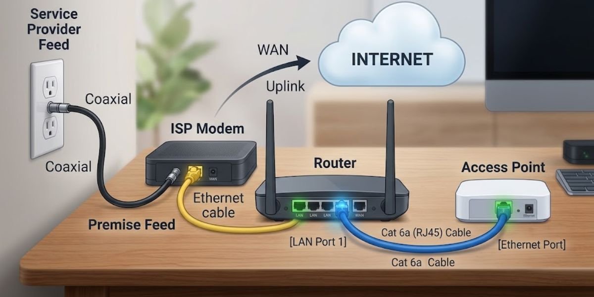
- Select one end of the Cat 6a cable and connect it to an open LAN port on the back of the home router. Do not plug this cable into the WAN or Internet port, as that interface connects to the upstream Internet service provider modem.
- Select the unattached end of the Cat 6a cable and connect it to the Ethernet interface on the wireless access point.
- Verify in the simulation view that the cable connectors drop cleanly into both ports and that the interface port highlights turn solid.
Ethernet, RJ45, and RJ11: Which Connection Should You Use?
The simulation shelf contains different cable types equipped with modular connectors that appear visually similar at a distance. Selecting the wrong cable prevents network link establishment.
Twisted-pair Ethernet cabling relies on RJ45 (8P8C) connectors, which feature eight conductor positions designed for network interfaces. In contrast, RJ11 connectors feature a smaller six-position housing typically used for analog telephone lines or DSL connections. Plugging an RJ11 connector into an RJ45 port results in an unstable physical connection and zero data transmission.
Coaxial cables utilize threaded F-type connectors designed for cable modems and television signals, making them incompatible with standard local area network Ethernet ports. Always choose the Cat 6a cable fitted with RJ45 modular plugs.
Powering On the Wireless Access Point
The access point requires external direct-current power to illuminate its status LEDs and initialize its internal radios.
- Retrieve the designated AC-to-DC power adapter from the shelf.
- Plug the barrel connector end of the power cable into the Power Input jack on the back of the wireless access point.
- Plug the two-prong or three-prong wall transformer end into an unassigned surge-protected outlet on the rack PDU.
- Confirm that the simulated power LED on the front panel of the access point transitions to an active state.
In commercial and enterprise environments, power distribution units (PDUs) supply centralized power to rack-mounted hardware. Managed PDUs offer network-based power cycling and telemetry, but their management functions operate independently of the client data traffic passing through the access point’s Ethernet cable.
Enabling the Laptop’s Wireless Network Adapter
With the physical infrastructure operational, you must configure the laptop client to communicate wirelessly. By default in this lab, the laptop’s internal wireless adapter is turned off at the hardware layer.
- Click on the laptop to open its physical workspace view.
- Hover over the exterior casing to locate the physical wireless switch (typically situated on the side or front edge of the laptop body).
- Toggle the switch to the ON position.
- Observe the physical status light near the switch to confirm that the wireless radio transmitter is active.
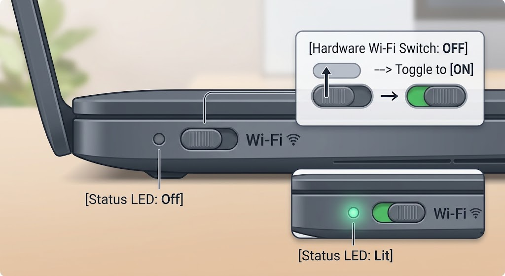
Enabling the hardware radio adapter provides power to the client’s internal 802.11 transceiver. Operating systems cannot scan for broadcast Service Set Identifiers (SSIDs) or process wireless frames while the underlying physical network adapter is disabled.
Connecting to the HomeNet-AC Wireless Network
After enabling the wireless adapter, transition to the laptop’s operating system environment to attach to the target wireless network.
- Open the laptop system screen inside the simulator.
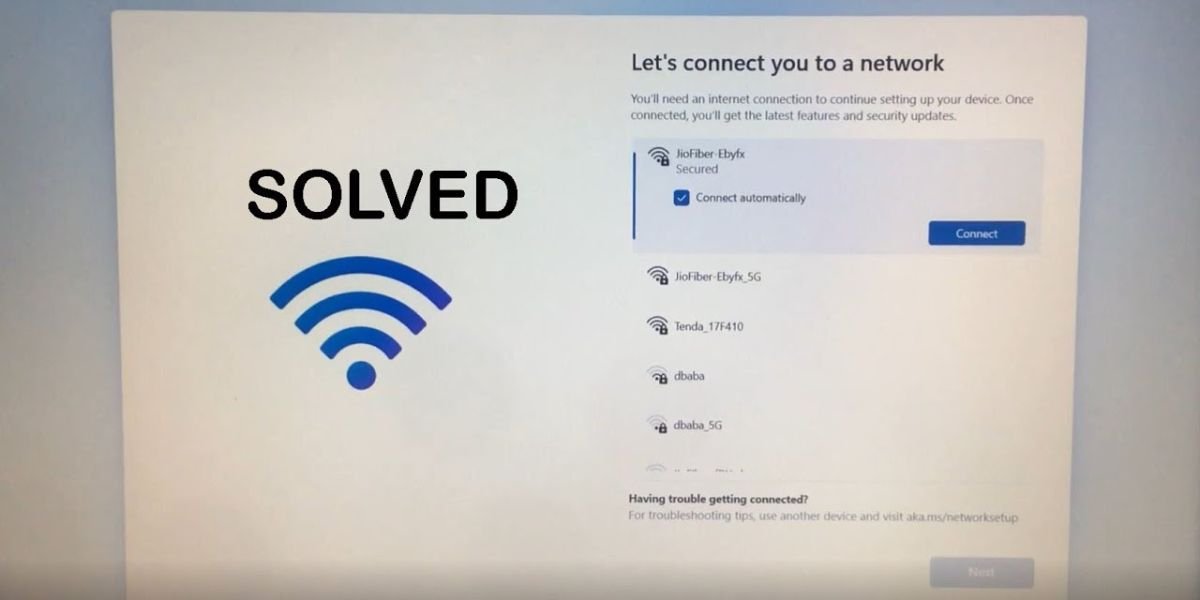
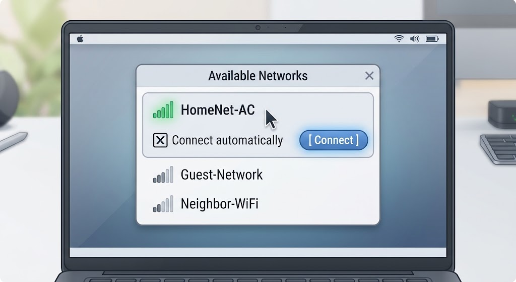
- Click the Network Status icon in the system tray to view the list of detected Wi-Fi networks.
- Locate and select the SSID named HomeNet-AC.
- Select the checkbox for Connect automatically.
- Click Connect.
- Wait for the operating system interface to complete association and update the network status display to Connected.
An SSID is an alphanumeric string up to 32 octets long that identifies a specific 802.11 wireless network. Selecting Connect automatically writes the SSID and its profile parameters to the operating system’s preferred network list (PNL), allowing the client to re-associate without manual intervention whenever the radio detects the access point.
Why the Automatic Connection Setting Matters
Configuring a client to connect automatically fundamentally changes how wireless network interfaces behave during system startup and roaming.
When Connect automatically is active, the wireless client constantly probes for beacon frames containing the saved HomeNet-AC SSID. As soon as the client enters radio range, it initiates the 802.11 authentication and association state machine in the background.
This setting operates independently of automatic IP addressing (DHCP). The automatic connection option manages layer 2 wireless link establishment, whereas DHCP operates at layer 3 to lease an IP address, default gateway, and DNS server parameters once the layer 2 link is stable.
Verifying That the Home Wireless Network Works
Confirming proper network installation requires validating link state and upstream network layer connectivity.
- Verify that the system tray icon displays solid signal bars indicating a successful 802.11 link.
- Open the simulated web browser on the laptop.
- Navigate to a test web address or execute the built-in lab verification utility.
- Confirm that the browser loads external page content, demonstrating that packets route successfully from the wireless client, through the access point, across the Cat 6a link to the router, and out to the WAN interface.
- Click the Done or Submit button inside the lab environment to record task completion.
Successful association to a wireless access point does not guarantee internet access. A laptop can maintain a strong 802.11 radio link to an access point while remaining unable to reach external web servers if the Ethernet cable between the access point and the router is damaged, disconnected, or plugged into an misconfigured port.
Troubleshooting Common Problems in the Lab
If the simulator does not award full credit upon completion, systematically diagnose the setup using standard network troubleshooting methodology.
The Wireless Access Point Does Not Power On
Verify that the power adapter is seated firmly into the DC barrel jack on the rear of the access point. Confirm that the power transformer is connected to an energized outlet on the PDU.
The Ethernet Cable Will Not Connect
Ensure you selected the Cat 6a cable equipped with RJ45 connectors from the shelf. Verify that the cable connects to a numbered LAN port on the router rather than an RJ11 telephone jack or the single WAN port.
HomeNet-AC Does Not Appear in the Wi-Fi List
Check the physical hardware switch on the exterior of the laptop casing. If the physical Wi-Fi switch is set to OFF, the wireless radio remains unpowered, preventing the OS network manager from discovering broadcast SSIDs.
The Laptop Connects but Cannot Access the Internet
Inspect the physical link between the access point and the router. Confirm that the Cat 6a patch cable is securely latched at both ends and that port link lights are active on both network devices.
The Lab Does Not Register as Complete
Review the explicit instructions in the prompt. Common missed steps include omitting the Connect automatically checkbox in the Wi-Fi connection window or selecting an access point that lacks 802.11b/g/n backward compatibility.
What This Lab Teaches About Real Home Wireless Networks
This simulation demonstrates core networking concepts that apply directly to enterprise deployment and real-world home office installations.
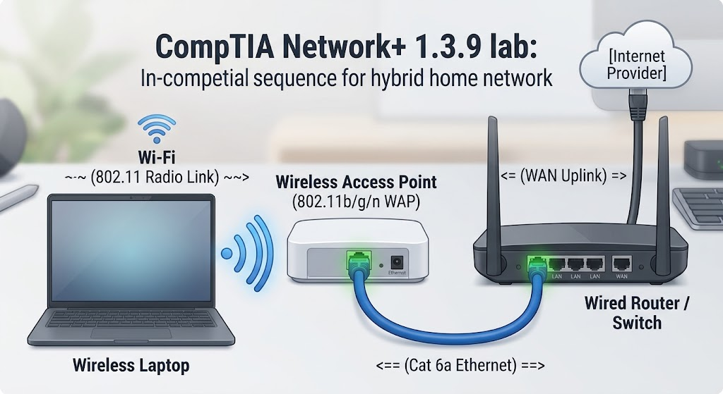
A standalone wireless access point (WAP) functions as a layer 2 bridge. It converts wireless 802.11 frames into wired 802.3 Ethernet frames and passes them to an existing network. A WAP does not perform Network Address Translation (NAT), serve as a DHCP server, or perform WAN routing on its own. Those tasks remain the responsibility of the central router.
In contrast, commercial consumer “wireless routers” integrate three separate hardware components into a single chassis: an IP router, a multi-port unmanaged Ethernet switch, and an internal wireless access point. Installing a dedicated access point, as done in this lab, represents the standard method for expanding wireless coverage across larger physical sites without introducing double-NAT routing conflicts.
A Security Note About Open Wireless Networks
In this CompTIA lab, the HomeNet-AC network is configured as an open network without authentication or encryption to focus strictly on physical and basic connection steps.
Deploying an unencrypted open wireless network in a real-world residential or corporate environment presents significant security risks. Open networks broadcast unencrypted payload frames across the open air, allowing unauthorized parties within radio range to capture unencrypted network traffic using packet analyzers.
Production wireless networks should always implement robust security frameworks:
- WPA3-Personal (SAE): The current standard for Wi-Fi security, utilizing Simultaneous Authentication of Equals to protect against offline dictionary attacks.
- WPA2-Enterprise / WPA3-Enterprise: Utilizes 802.1X authentication with a centralized RADIUS server for corporate credential verification.
- Strong Passphrases: Wireless networks using pre-shared keys should enforce complex passphrases to prevent brute-force cracking.
- Administrative Hardening: Default administrative passwords on access points and routers should be changed immediately upon deployment to prevent unauthorized configuration changes.
Frequently Asked Questions
Which wireless access point should you select for the 1.3.9 lab?
Select the access point that explicitly lists support for 802.11b/g/n standards and supports maximum theoretical data rates up to 600 Mbps.
Why does the lab require backward compatibility with the 2.4 GHz band?
Legacy clients using 802.11b or 802.11g network adapters can only communicate across the 2.4 GHz frequency spectrum. Selecting an 802.11b/g/n access point ensures both legacy 2.4 GHz and modern 5 GHz devices can associate with the network.
Which Ethernet cable is used to connect the access point to the router?
Use the Cat 6a Ethernet cable fitted with RJ45 modular connectors found on the equipment shelf.
Why must the laptop’s wireless adapter be enabled before connecting?
The physical hardware switch controls electrical power to the laptop’s internal wireless network card. When disabled, the radio transceiver cannot broadcast probe requests or detect access point beacon frames.
What does the “Connect automatically” setting do?
Enabling Connect automatically saves the HomeNet-AC network profile to the operating system’s preferred network list, allowing the laptop to initiate background layer 2 association whenever it detects the SSID.
How can you tell whether the lab is complete?
Completion is verified when the laptop displays an active Connected status to HomeNet-AC, successful web page rendering confirms upstream Internet routing, and the simulation interface reports a score of 100%.