Plugging a standard network cord into an uninterruptible power supply often leads to immediate frustration. The back panel of the APC Back-UPS XS 1500 (sold under model numbers BX1500 and its later, more efficient revision BX1500G) carries jacks that look almost identical to a home router’s Ethernet ports, so it’s an easy assumption that a spare network cable will link the unit to a computer or a home network.
That assumption is wrong, but not for the reason a lot of older troubleshooting guides describe. This unit doesn’t hide a proprietary 10-pin signaling jack behind a look-alike Ethernet port. Its computer link is a completely ordinary USB port. The RJ11 and RJ45 jacks on the back exist for a different job entirely: shielding your modem, router, or fax line from surges that travel in through the phone or network wiring itself, sometimes called back door surges. APC (now a brand of Schneider Electric, which acquired American Power Conversion in 2007) documents this pairing directly in its official spec sheet for the unit, listing “Data-line Protection” as coverage for Ethernet, coaxial, and phone lines, separate from the battery and monitoring electronics.
Mixing up the two functions won’t damage anything electrically, but it will leave you wondering why Windows never shows a UPS device, or why your internet connection suddenly feels slower after “helpfully” rerouting cables. Understanding what each port actually does gets your monitoring software talking to the UPS and keeps your networking gear properly shielded from lightning-induced spikes.
The XS 1500 Has Two Different Types of Network-Style Connections
The rear panel splits into two functional zones that have nothing to do with each other. One is a plain USB data port that reports battery status to a connected computer or NAS. The other is a pair of RJ11/RJ45 surge-suppression jacks that protect a phone line or Ethernet run from voltage spikes as it passes through the unit.
They’re easy to confuse because APC’s own documentation and marketing copy both use the word “port” loosely, and older Back-UPS and Smart-UPS models really did use signaling jacks that resemble phone or network connectors. But on the Back-UPS XS 1500 specifically, the computer-facing connection is USB, full stop. That single fact resolves most of the confusion people run into with this model.
The RJ50 Data Port for Computer Communication
A lot of general APC troubleshooting content mentions a proprietary 10-pin RJ50 data port wired with a 940-0127 or AP9827 cable, and it’s worth clearing up where that information actually applies before it sends you looking for a part your unit doesn’t need.
That RJ50 signaling jack is real, but Schneider Electric’s own support documentation confirms it belongs to a different slice of the APC lineup: certain Smart-UPS models and units paired with a Network Management Card use the 10-pin connector, while “some Back-UPS units use a standard USB-A to USB-B cable” instead, according to Schneider Electric’s official FAQ on Back-UPS communication cables. The Back-UPS XS 1500 falls into that second group.
You can confirm this yourself two ways. First, the unit’s own printed manual, APC’s Back-UPS RS/XS 1200/1500 User’s Manual, shows a “To Computer USB” connection point in its wiring diagram, distinct from the separate RJ-11 and RJ-45 jacks used for phone and network surge protection. Second, Network UPS Tools (NUT), the open-source project maintained by the free software community and widely used on Linux servers and NAS platforms, lists the Back-UPS XS 1500 on its hardware compatibility page as working with the usbhid-ups driver, the same driver used for any generic USB Human Interface Device. There’s no serial or RJ50 driver involved because there’s no RJ50 hardware to drive.
So if a listing, forum post, or older article told you this unit needs an AP9827 or 940-0127 cable, that’s advice written for a different APC product family. Your XS 1500 already has the simpler connection.
The RJ45 In and Out Ports for Ethernet Protection
The RJ-45 jack pair (and the accompanying RJ-11 jack for phone lines) sits completely apart from the battery and signaling circuitry. These connectors pass data straight through an internal clamping circuit built to suppress high-voltage transients arriving over the copper wiring itself, then send the traffic on to your router, modem, or fax machine unchanged.
APC’s own feature list for the Back-UPS XS line describes this as protection for “Ethernet, Coaxial and Phone lines,” framing it explicitly as a defense against surges that sneak in through data cabling rather than through the power cord, a real and well-documented risk during storms when a strike hits a utility pole carrying both power and telecom lines. Because the circuit operates independently of the microprocessor that tracks battery charge and runtime, plugging your PC into these jacks instead of the USB port won’t hurt anything, it just won’t produce any status reporting either.
On most APC surge-protection blocks the two matching jacks are grouped as an incoming line and an outgoing line to the protected device, sometimes silkscreened as IN and OUT, other times shown simply as a wall-side jack and an equipment-side jack in the manual’s diagram. The wiring principle is identical either way: whatever comes in from the street gets clamped and passed along, so plug the live line from your ISP’s demarc, DSL jack, or phone wall plate into the first jack, then run a second cord from the paired jack to your modem, router, or fax machine.
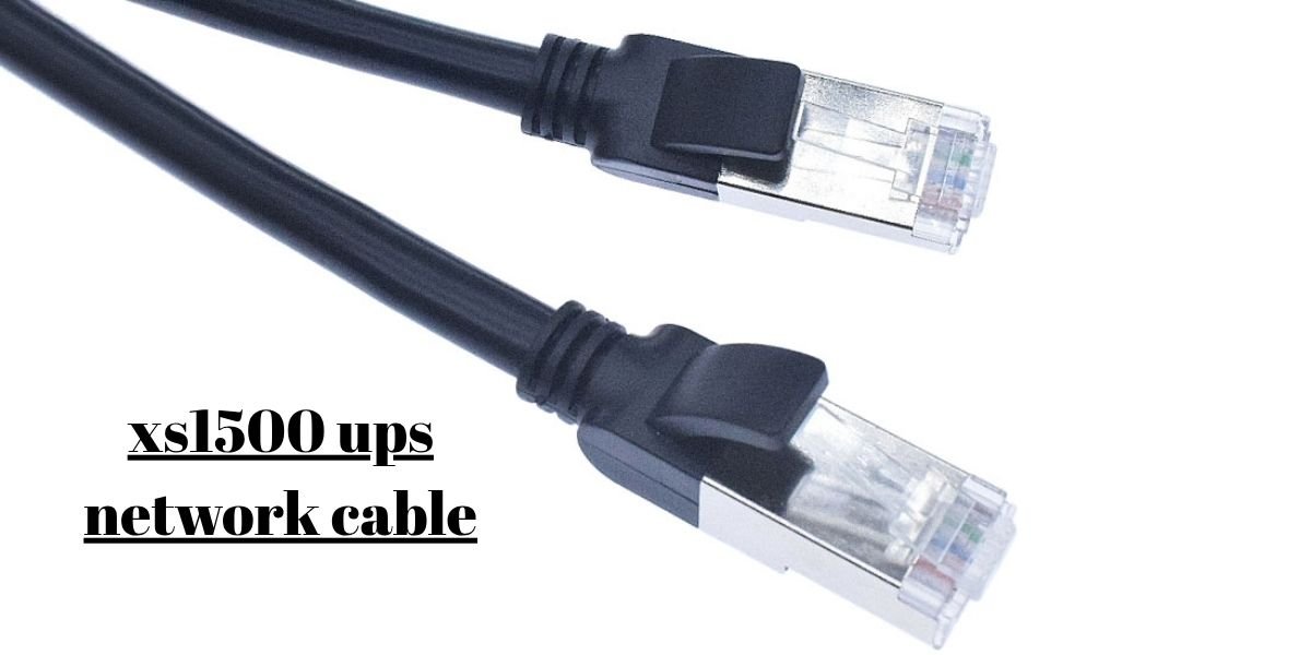
Standard Cat5e or Cat6 patch cords work perfectly fine here, and running data through this pair does not reduce network speed. The clamping components only activate during an actual voltage anomaly; under normal conditions, the signal passes through with no measurable added latency.
Which Cable Does the XS 1500 Data Port Use?
Since the “data port” on this unit is a genuine USB connector, the cable requirement is refreshingly ordinary: a standard USB-A to USB-B cable, the same style long used for printers, external hard drive enclosures, and many audio interfaces.
This matters because it directly contradicts advice aimed at Smart-UPS or Network Management Card products that do require the 10-pin RJ50-to-USB adapter cable. Schneider Electric’s support team addresses exactly this fork in the road, noting that while “many Back-UPS use cable 940-0127, which is USB A to RJ50,” other Back-UPS models, including the USB-equipped consumer units like the XS 1500, “use a standard USB-A to USB-B cable” (per Schneider Electric’s cable FAQ). The unit’s retail packaging bears this out as well; product listings for the BX1500G list a “Power Saving Back-UPS XS 1500 USB Cable” as an included accessory alongside the printed manual, not a proprietary signaling lead.
Practically, that means you’re not locked into buying a $15 to $35 branded replacement if the original cord goes missing. Any well-made USB-A to USB-B cable from a reputable electronics retailer will work, typically running $5 to $12 for a 6-foot length. Avoid cheap “charge-only” USB cables sold for phone chargers, since some of those omit the internal data wires entirely and will power the connection LED without ever registering a device in Windows Device Manager or a NAS’s USB device list.
Connecting the XS 1500 to a Computer or NAS
Setting up a monitoring link takes only a couple of minutes once you know you’re dealing with plain USB rather than a specialty adapter.
Connect the UPS Data Port to USB
Plug the USB-B end of the cable into the port on the rear panel labeled for computer connection, then plug the USB-A end into an available USB port on your desktop, laptop, rackmount server, or NAS. A direct motherboard or chassis port is preferable to an unpowered USB hub, since some hubs don’t reliably pass through the HID signaling the UPS uses to report status.
Windows recognizes the device automatically without any driver download, because it enumerates as a standard HID-compliant UPS battery device. A real-world installation walkthrough documented by InformatiWeb shows Windows identifying a connected Back-UPS unit by its exact model and firmware string the moment it’s plugged in, with no manual driver installation required. NAS platforms behave the same way: Synology DSM and TrueNAS both scan for USB HID power devices and will log a newly recognized UPS in their respective system event logs within seconds of connection.
Use UPS Software for Monitoring and Shutdown
APC’s own client-side tool for this UPS family is PowerChute Personal Edition, described on APC’s official product page as free shutdown and monitoring software built for home computers and battery backups. It shows live input voltage, battery charge percentage, estimated runtime under the current load, and a running log of power events like brief outages or brownouts.
Linux users and NAS owners generally reach for the open-source alternatives instead: Network UPS Tools (NUT), already mentioned above for its confirmed compatibility with this exact model, or apcupsd, a long-running community-maintained daemon built specifically around APC’s USB and serial UPS protocols. Both read the same HID status stream the Back-UPS XS 1500 exposes over USB, so no APC-branded software is strictly required to get full telemetry.
Whichever tool you choose, the meaningful payoff is configuring an automated shutdown threshold. A typical setup tells the connected machine to begin a graceful operating system shutdown once the battery drops to somewhere around 10 to 20 percent remaining capacity, or after a set number of minutes running on battery power, whichever comes first. That window is enough time for open files to save and file systems to unmount cleanly, which matters most for a NAS running a live parity array or a server holding an open database, where an abrupt power cut is far more likely to cause corruption than the same event on a machine that shuts down in an orderly sequence.
Beyond emergency shutdowns, leaving the USB link connected long-term has a quieter benefit: the event log itself becomes a diagnostic tool. Frequent “on battery” transitions logged by PowerChute or NUT usually point to a utility circuit prone to brownouts or voltage sag, information worth knowing before it causes a hard crash on equipment that isn’t behind a UPS at all.
Using the XS 1500 for Ethernet Surge Protection
Getting the surge-protection side of the unit right just requires keeping the network cabling on its own pair of jacks, separate from the USB monitoring connection described above.
Connect the Network Line to the IN Port
Take the incoming line, whether that’s the cable coming from your wall jack, your cable or DSL modem, or the demarc point where your provider’s service enters the building, and plug it into the jack intended for the incoming connection on the rear surge-protection block.
Check the link lights on your modem or router to confirm the connection is active before moving on. Routing the incoming line into this jack first matters because it puts APC’s internal metal-oxide varistors between the outside line and everything downstream, so any transient riding in on that cable gets clamped before it ever reaches your equipment.
Connect the Protected Device to the OUT Port
Run a second Cat5e or Cat6 patch cable from the paired jack on the surge block to the Ethernet port on your router, switch, or desktop PC.
Once both ends are seated, run a quick speed test or file transfer to confirm normal throughput. A properly wired pass-through introduces no noticeable slowdown; if you do see degraded performance, it’s far more likely due to cable quality or a loose connector than the surge circuitry itself.
Can You Use a Regular Ethernet Cable With the XS 1500?
The honest answer depends entirely on which port you’re asking about.
For the RJ45 surge-protection pair, yes: a standard Cat5e or Cat6 Ethernet cable is exactly what these jacks are designed for. They use conventional wiring, so any off-the-shelf patch cord will pass data through the surge-suppression circuit without issue.
For the computer monitoring connection, an Ethernet cable is the wrong tool entirely, but not because of a mechanical pin mismatch as older troubleshooting write-ups sometimes describe for RJ50-equipped models. On the XS 1500 there’s no oversized 10-pin jack to physically confuse with an 8-pin RJ45 plug in the first place, because that port is USB. Plugging a network cable into a USB-B socket isn’t physically possible, which actually makes this model harder to miswire than the Smart-UPS units that genuinely do share a look-alike jack shape between their signaling and Ethernet ports.
The practical takeaway: keep your Ethernet cables on the surge-protection jacks and your USB cable on the monitoring port, and there’s no ambiguity left to troubleshoot.
Choosing a Replacement Cable for the XS 1500
If the original cord that shipped with your unit goes missing, the replacement shopping list is short.
Confirm the listing specifies a USB-A to USB-B cable, not a USB-A to RJ50 signaling cable. The 10-pin RJ50 cords sold under APC part numbers AP9827, 940-0127, and 940-0127B are built for Smart-UPS and Network Management Card products and simply won’t plug into anything on the back of a Back-UPS XS 1500, since there’s no RJ50 jack present to accept them.
A basic printer-style USB-A to USB-B cable in the 6-foot range covers virtually every desktop or NAS placement scenario without needing an extension. Length matters more than brand here; unlike high-speed data cables, a UPS status link runs at low bandwidth, so an inexpensive, well-shielded cable performs identically to a premium one.
If you’re shopping for a replacement for the RJ45 surge-protection side instead, any certified Cat5e or Cat6 patch cable works, and there’s no APC-specific part number to look for since that circuit accepts standard networking cable by design.
Common XS 1500 Cable Problems
Most connection issues with this unit trace back to one of a small handful of causes, and none of them require replacing the UPS itself.
The Computer Does Not Detect the UPS
Start by moving the USB cable to a different port, ideally one built directly into the motherboard rather than a front-panel header or an unpowered hub. USB hubs occasionally fail to pass through the HID enumeration the UPS relies on to identify itself.
Next, confirm the monitoring software’s background service is actually running. Restarting the PowerChute service in Windows Services, or restarting the apcupsd daemon on Linux, often re-establishes a lost connection without a full reboot.
On Linux or a NAS shell, running lsusb should return a line referencing American Power Conversion. If nothing shows up at all, try a different cable before assuming a hardware fault. A worn or low-quality USB cable, especially one salvaged from an unrelated device that skimped on internal data wiring, is a more common culprit than a failed UPS.
The Cable Fits but Does Not Communicate
Because the XS 1500 uses a standard USB-B connector, a cable that seats properly but still fails to communicate is usually one of two things: a charge-only USB cable missing the internal data conductors, or a cable with a worn or bent USB-B connector that’s making an unreliable contact.
You can rule out the first cause quickly. Charge-only cables are common in bundled phone chargers and typically only carry two of the four wires a proper USB data cable needs. If Device Manager in Windows shows the device connecting and disconnecting repeatedly, or a NAS logs a connect event with no corresponding UPS entry, swap in a cable you know supports full USB data transfer, such as one that came with a printer or external drive.
Ethernet Protection Is Not Working as Expected
If network speeds seem to drop after wiring through the surge block, or a connected device won’t establish a link at all, double check which jack carries the incoming line. Reversing the cabling, so that the local computer’s cable lands in the jack meant for the incoming service and the internet-facing line lands in the equipment-side jack, can interfere with Ethernet’s auto-negotiation handshake on some hardware.
Reseat both patch cables fully; a connector that isn’t clicked in all the way is a frequent cause of intermittent link loss that looks like a surge-protection fault but is really just a loose plug. If problems persist after confirming correct orientation and a solid connection, swap in a fresh, factory-terminated Cat6 cable. Worn or hand-crimped patch cords are a far more common source of packet loss on a passthrough circuit like this one than any fault in the surge-suppression components themselves.